
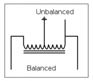
Balun, a three-port broadband RF transmission line transformer
By converting the match input to differential output
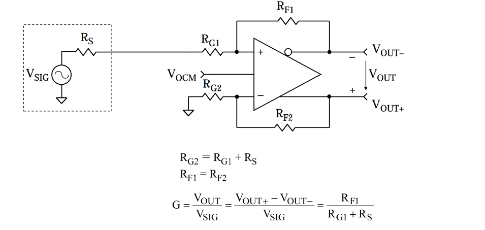
to achieve a balanced connection between the transmission line circuit and the unbalanced transmission line circuit
Make the system with different impedances or be compatible with differential/single-end lettering

For modern communication systems such as mobile phones and data transmission networks
In this article, you'll learn about Barron's:
The underlying functionality
Several types
Common uses
Actual use
Basic principle
and performance metrics
1. Switch current or voltage from imbalance to equilibrium
2. Common-mode current suppression is performed by some constructions
3. Impedance conversion by some constructions (impedance ratio is not equal to 1:1)
There are several types
1. For impedance conversion, impedance matching, DC isolation, and matching of balanced ports to single-end ports are possible. Impedance conversion Balun common mode choke is also, in a sense, a Balun because it eliminates common mode signals.
2. Used to connect transmission lines with different impedances.
Balun is designed for push-pull amplifiers, broadband antennas, balanced mixers, balanced multiplifiers and modulators, phase shifters, and any circuit design that requires equal range of transmission on both lines and a phase difference of 180 degrees.
Connect an unbalanced signal to a balanced transmission line for long-distance transmission.
Differential signaling with balanced transmission lines is less affected by noise and crosstalk, uses lower voltages, and is more cost-effective than single-end signaling with coaxial cables.
As a result,Balun can be used as an interface between local video, audio, and digital signals and long-distance transmission lines.
Radio
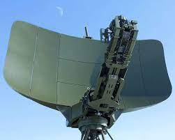
Radar
Transmitter
Satellite

Telephone network
Wireless network modem /router
Basic principle
The ideal S parameter
S12 = -S13 = S21 = -S31
S11 = -∞
Balun's two output amplitudes are equal, and the phases are opposite:
- In the frequency domain, this indicates a phase offset of 180 degrees between the two outputs;
- In the time domain, this means that the voltage of one balanced output is negative for the other.
In addition, the conductor of one of the two lines must be clearly grounded.
The balancing line consists of conductors with equal amplitudes and opposite phases.
Because microseeds and coaxial cables use conductors of different sizes, they can be described as unbalanced lines.
Balun is designed to address the problemscaused by such unbalancedlines, which can be converted between a balanced (or differential) transmission line in which current is transmitted in opposite phases and an unbalanced (or single-end) transmission line where the return current is transmitted underground.
Inside the coaxial cable, the two current amplitudes are equal and the phase is opposite because the electric field generated by the current inside the inner conductor and the shield is confined to the space between the two.
At the same time, the skin-warming effect causes another current to be generated on the outside of the shield, and when the current is large, the coaxial cable acting as a feeder wire can become an antenna, and the outward radiation intensity is directly related to the current size of the electromagnetic field.
Because coaxial cables have symmetrical physical structures and have equal circuit amplitudes and opposite phases on their internal conductors, their internal structures themselves produce very little radiation.
However, certain factors can disrupt the current balance in their two conductors (i.e., the state of "equal amplitude, opposite phase"), in which case the inside of the feeder will also produce greater electromagnetic radiation as the current on the outside of the shield.
This imbalance causes distortion, interference, and loss of the direction map.
Key specification parameters for determining the Balun type for specific applications include:
• Frequency coverage
• Phase equilibrium
• Amplitude equilibrium
• Common mode suppression ratio
• Impedance ratio / number of times ratio
• Insertion loss and echo loss
• Balance port isolation
• DC/ground isolation
• Group delay flatness
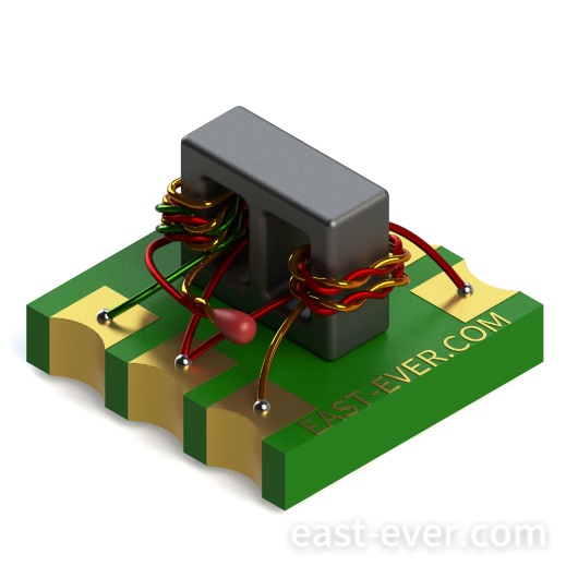
Balun is divided into several types, and the type of Balun used in microwave RF design depends on the required bandwidth, frequency of operation, and the physical structure of the design. Most Balun interiors usually contain two insulated copper wires that are stranded with each other and wrapped around magnetic or non-magnetic cores.
Key specification parameters for determining the Balun type for a particular application include:
• Frequency coverage
• Phase equilibrium
• Amplitude equilibrium
• Common mode suppression ratio
• Impedance ratio / number of times ratio
• Insertion loss and echo loss
• Balance port isolation
• DC/ground isolation
• Group delay flatness
An important standard indicator of Balun is its equilibrium, i.e. the proximity of two equilibrium outputs (one is an inverse 180-degree output and the other is a non-inverse output) to the ideal state of "power level equal, phase difference of 180-degrees". The phase angle difference between the two outputs and the degree of deviation of 180 degrees is called the phase imbalance of Balun.
This metric is determined by Balun's structure and line matching, usually in dB. Amplitude balance refers to the match between the size of the output power, and the difference between the two output power sizes is called amplitude imbalance in dB. In general, the common mode suppression ratio (CMRR) increases by 0.1dB for every 0.1dB increase in amplitude, or 0.1dB for every 1 degree increase in phase balance.
When two identical signals with the same phase are injected into balun's balanced port, two different results may be emitted or received. CMRR refers to the amount of attenuation, in dB, that occurs during the transmission of the signal from the balanced port to the unbalanced port. The CMRR is determined by the addition of vectors from these two signals, which further depends on Balun's amplitude and phase equilibrium.
The ratio of unbalanced impedance to equilibrium impedance is usually expressed as 1:n.
Differential impedance is the impedance between balanced signal lines and twice the ground impedance of the signal line.
The number ratio is a parameter of the flux-coupled Balun transformer, which represents the ratio of the primary winding number of the transformer to the number of secondary windings.
The square of the ratio is equal to the impedance ratio, for example, when the ratio is 1:2, the impedance ratio is 1:4.
Balun with a high impedance ratio can be designed with a flux-coupled transformer.
The lower the differential insertion loss and the higher the common mode echo loss, the greater the insertion signal power through Balun, the wider the dynamic range, and the less distortion of the signal.
In an ideal Balun without isolation, the common mode signal can be fully reflected by 0dB of echo loss,while the differential signal passes through the echo loss of- ∞.
Balanced port isolation refers to the insertion loss, in dB, from one balancing port to another.
Because most Balun reflects the even mode rather than properly ends it with a resistive load, its balancing port isolation is not high.
One exception is a 180-degree hybrid circuit that outputs even modes to ports that can be resistively terminaled.
The type of Balun used in microwave RF design depends on the required bandwidth, frequency of operation, and the physical structure of the design.
The Balun types that can be used for differential power distribution purposes are transformer Balun, capacitor and/or magnetically coupled transmission line Balun, hybrid coupler Balun, and such Balun can also be used in the case of amplifier and inverter coupling.
Versatile
Conversion from down to single-end signal and differential signal, up to mode noise and signal elimination.
For Balun, the most important characteristics are its power balance and phase balance.
The flux-coupled transformer Balun is the most common type of Balun, consistingof a core and two different wires wound to the core, where the primary winding is grounded on one side to create an imbalance condition on the primary side and a balance condition on the secondaryside. The ratio of the number of secondary side turns to the number of primary side turns can be set arbitrarily, resulting in any required impedance ratio. The AC voltage produced by the secondary side of the magnetically coupled Balun transformer is n times the voltage on the primary side, and the current is correspondingly 1/n of the primary side current, thus producing n2 times the output impedance, where n is the ratio of the secondary side turn to the primary side.
The secondary windings of the winding flux-coupled transformers are usually equipped with grounded center nods, which improves output balance.
Example
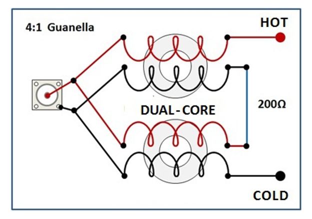
Flux-coupled transformers are best suited to operating at frequencies below 1GHz and often have coupling losses when operating at higher frequencies. At microwave frequencies, the loss angle of the magnetic material in the transformer is being cut higher, resulting in a large signal loss.
As a result, capacitive coupling transmission lines such as Guanella Balun,which typically consist of two transmission lineswrapped aroundthe core, solve these problems at highfrequencies through low-frequency magnetic coupling and high-frequency capacitive coupling.
One type of Balun that is often used in microwave applications is MarchandBalun. The video "All Kinds of Spiral Balun"presents an overview of the intersection,symmetry, and Marchand spiral Balun, as well as the design and simulation results of the GaAs MMIC plane spiral Balun.
Classic transformer Balun
A classic transformer, also known as an isolation transformer, has two separate coil windings wrapped around the transformer core, which can be neither empty (air core) nor magnetic neutral materials such as ceramics, magnetic conductors or soft iron. Where the primary winding receives the input signal, and the secondary winding output converts the signal. In an ideal transformer, the ratio of voltage to current is always directly related to the square of the winding ratio, and the power (in watts) is always the same.
Pros: Because of the electrical isolation between the input winding and the output winding, the Balun can be used to connect circuits with ground circuit problems or electrical incompatibilities with ground flat voltages.
Self-coupled transformer Balun(voltage Balun).
The self-coupled transformer Balun has one coil, or two or more coils, and the electrical wiring of these coils is also wrapped around the ferrical core or ring core. When there is only one winding, at least one additional electrical connector or tap must be set between the ends of the winding. In This Balun, the input current entered by a pair of electrically connected wires acts as a primary coil and is used for the magnetization of the core.
Pros: Unlike other transformer types, the self-coupled transformer Balun grounds the DC current at all ends.
Transmission line transformer Balun( Choke Balun)
This type of Balun, sometimes called current Balun,guarantees an equal output current between the two outputs, but notnecessarily the same output voltage. The current inside the coaxial cable is equal in size and in the opposite phase, so that the magnetic field produced is equal in strength and in the opposite direction, and in most cases can cancel each other out. When the transformer Balun is combined with the transmission line transformer Balun, a very wide working bandwidth is achieved. Guanella transmission line transformers and Balun combinations are often used as impedance matching transformers.
Pros: Choke Balun prevents additional current from flowing back along the transmission line through inductive impedance.
Delay line Balun
The delay line Balun is connected to a transmission line with no transformer device and a specific length, typically used for a narrow frequency range where the connected transmission line is a multiplied number of a quarter of the wavelength of the target frequency within the transmission line medium. This type of Balun is used for coaxial connections to transfer to a balanced antenna.
Pros: Produces a phase offset of 180 degrees and provides a balanced input.
Self-resonant Balun
In transformers made of physical materials, there is a small amount of capacitance between the primary and secondary windings and between the wire coils within the windings, which form undesirable self-capacitors or parasitic capacitors.
Resonance occurs when the self-sensing and self-capacitor resistances in Balun are equal in size and opposite in nature.
Baluns of any design type do not perform well when working at frequencies equal to or higher than resonant frequencies.
Balun was designed with the consideration of making it as resonant as possible much higher than the working frequency.
As the frequency increases, the impedance of the parasitic capacitor decreases gradually until it is equal to the impedance of the ideal inductor at the self-resonant frequency (SRF).
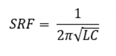
Therefore, the effect of the above inductor is like that of an inductor with a self-resonant frequency as the critical value, and once the value is exceeded, the impedance rises sharply. Moreover, the inductor can be used as a choke to attenuated signals near the self-resonant frequency.


